Building an automatic plant waterer (2/?): resistive sensing

This was harder than I expected.

  • Part 1: resistive sensing
  • Part 2: finding resistive sensing is bad and capacitive sensing is hard
  • Part 3: another crack at a capacitive sensor
  • Part 4: calibrating the sensor

Day III (weekend 3)

Not really much time this weekend. I pulled out the electrode and (it had been sitting there unpowered) and saw this:

Snapchat-910764504

Copper salts deposited on the electrodes. It was really hard to get my phone to reproduce the colour.

It looks like corrosion has already started. There’s not much but it’s only been there a few weeks and has probably spent a few of hours powered by now. With my current plan (maybe waking up every 30 minutes), the amount of time ‘on’ would be about 16 minutes per day (10 seconds of higher current charge in each direction). That’s only a week or two before it reaches these levels of corrosion. So, that I think precludes 10 second measurements, or at least 10 seconds of direct charging without a resistor in the way.

Day IV (Weekend 4)

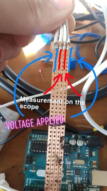
Wow really not getting as much time on this as I’d like. So, what about capacitive measurements? Having insulated electrodes should preclude any corrosion problems and I’ll bet that using soil as dielectric will increase the capacitance as the water content increases. First, an initial experiment:

capacitor-1

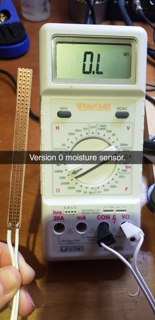
The sensor is a bit of electrical tape over some strip board.

This indicates we’re into the realms of possibility, though the number of picofarads is still small enough to be pretty irritating. It’s also a pretty useless soil sensor: soil/water get through the holes behind and the result is a measurable resistance between the electrodes (about 9M or so). And the insulator is pretty thick which is going to make the capacitance low and reduce the sensitivity.

I do have some enameled wire in various grades. The finest (0.14mm) has a very thin coating. I made a couple of different sensors using the wire, mostly wrapping it around lots to get a decent surface area:

Snapchat-605221828

A couple of attempts at a capacitive sensor. Left, interleaved wires, right the two plates are well separated.

One slight problem: it doesn’t measure open circuit; there’s about 15M between the two sides, rising as it dries off. The flat one measures about 28pF when in the air, and about 280 in damp soil, rising to about 2nF when just watered. Unfortunately I don’t know how much the resistance is affecting this, so I’m going to have to try again. I’m going to try the next thicker grade of wire I have (0.23mm) and incidentally it has a different color coating.

Having a nice large spacing between the two plates seemed to work well in that it was easy to clean and reset back to the dry state. So, on to version 2:

Snapchat-2045180743

Version two of the sensor with thicker wire and nicely soldered joints. 40 turns of wire in each section.

As a reminiscent aside, I remember soldering lacquered wire back in the olden days with my fixed temperature iron. I could never settle on fine sandpaper versus a flame to remove it. Those days I do not miss, now I just crank up the iron temperature.

Anyway this seems to be going better: the resistance is greater than 2G. I think I might have mentioned it before but my multimeter skipped leg day. It can measure up to 2GOhm, but only down to 20mA. Weird. On to the capacitance measurements. So they are:

  • BOGUS! that’s what they are, bogus!

Well shoot. It seemed to be working great, but after a bit of use the resistance is back to being about 10M. That’s disappointing. OK, try3! I’m going to wrap the wires longitudinally so that they never even cross:

WLPjJ2i

I forgot to take a picture of it! Look at the “fix” below with hot-melt to get the idea.

Anyway the wires are always separated by about 4mm. So the measurements are:

  • First use: 12pF
  • Finger lightly on one side: 28pF
  • Fingers pressed on both sides: 100pF
  • Damp soil: 185pf, 233pF, 202pF, 190pF
  • Slightly compacted damp soil: 323pF,
  • Same place during watering: 680pF
  • Resistance: 12M

orly

OK well, this is getting suspicious. The 20M range is maxed out. But the 2G range reads low (there’s nothing in between, that’s only a few % difference). Now the capacitance reads in the nF range as well. Hitting it with a heat gun seems to reset everything.

So putting a blob of water on in the middle doesn’t do anything. Butting a blob of water on the end where the wires are bent round quickly drops the resistance back town to 10M. I think the act of wrapping the wire breaks the insulation very slightly. Well, that’s irritating. Let’s see:

Fixed with hot melt

If you use hot melt and don’t have a reflow style hot air gun, you’re really missing out.

OK, so the new measurements:

  • Damp soil: 250pF, 360pF
  • During watering: 1nF
  • After watering: 600pF and dropping
  • Resistance: 𝟚𝟘𝕄

rage

Apparently there is something hot-melt can’t fix. Observing more, the resistance is climbing very slowly, up to 26 now, now 40. Well, it might not matter. If I keep my measurement resistors well under the 20M range (say 200k), then the small error incurred due to leakage won’t matter. Still, I’d prefer to have it work properly.

So where are we? The capacitance sensor definitely works after a fashion, but we need to measure it. It bottoms out at 30pF, and is well into useful readings at about 300pF or so. I think I could get away with a 1M resistor safely. For an RC circuit, that would give a time constant of about 30us, which is small, but that’s at the 0 end of the range. It’s just about measurable on an Attiny85 with the 16MHz clock.

Additionally, the Attiny85 has a built in comparator. So, my current mental design has a relaxation oscillator in mind: charge up the capacitor through a 1M resistor, then discharge through a GPIO pin once the voltage crosses a threshold.

Sounds like a plan.

Building an automatic plant waterer (1/?): resistive sensing

This turned into a saga. Naturally this is Part 1.

  • Part 1: resistive sensing
  • Part 2: finding resistive sensing is bad and capacitive sensing is hard
  • Part 3: another crack at a capacitive sensor
  • Part 4: calibrating the sensor

This is a blow-by-blow account rather than a neat design story, so you get to see the experiments I did to prove/disprove ideas and the dead ends that I went down. All the dead ends. So many…

Day 1

I bought a pitcher plant. Unfortunately it turns out that I am less good at remembering to water it than I fooled myself into believing. So, instead of watering it, I’m in my lab building a device to water it for me. I’m also engaging in the entertaining game of minimizing the BoM on the electronics side as much as possible. My current thought is an old 12V supply, an attiny of some sort, a MOSFET, a soil probe and a peristaltic pump.

Through the magic of the internet I have some supplies:

A peristaltic pump (12V), some T-adapters which were supposed just be couplers but I must have ordered the wrong ones and some slightly odd sized tube because the tube I ordered did not arrive.

The pumping hardware

I ordered a series of tubes

And because I have to take everything apart, here’s the pump:

There are no gears. There are only 12 parts (motor, 2 screws, mount, case top, case bottom, 3 rollers, roller holder and tube). Compare this to the older design of cheapie peristaltic pump:

snapchat-57267770

Old cheap peristaltic pump.

The old design is more complex. It also noisier and doesn’t run as smoothly, it’s harder to put the tube in and it has a real tendency to split tubes if they’re not precisely the right size. I like the new design.

Exploration

The next bit is to figure out the moisture sensor. I’m going to measure the resistance between two conductors (on stripboard). Firstly, splitting a chunk off by bending it over in a vice is less reliable than I thought it might be…

Unreliably split stripboard.

Yuck.

Pre-scoring it heavily, then filing after was tedious but ultimately gave a much cleaner cut:

snapchat-786624393

Now to try it on a victim plant. It’s a fuchsia which I’ve propagated from cuttings and I’ve been keeping indoors. I’ve not watered it in a while, so it’s very dry. I made a bunch of measurements with a spacing zero and 1 columns between the electrodes.

Interestingly it didn’t make all that much difference. Either way the resistance was between about 0.8 and 3.3MΩ. Now for the other end of the scale:

snapchat-2013458458

Of course I didn’t wait half an hour. I waited more like an hour. Either way the moisture looks like it’s thoroughly propagated around. Time to measure. First a spacing of one row:

snapchat-1311116043

Interestingly, the resistance takes ages to settle, on the order of minutes where it keeps changing. The direction depends on the measurement range, so I suspect there’s some sort of electrochemical effect going on. Brief pulsed measurements (as brief as I can get) on the 200K range give about 30K resistance, but it rapidly climbs. On the 200k range long term it gives, well,  it’s up to118K and climbing very slowly. On the 2M range long term it gives about 62K resistance.

Now I find it’s a dodgy battery

And guess what! It’s a cell apparently (my trusty old multimeter has a 2GΩ range but nothing below 20mA. I think it skipped leg day):

Interestingly, measurements “shortly” after shorting it (hee hee) are also around 30k. Maybe less. There’s actually something interesting going on here, and it’s too fast really to see on one of these multimeters. Plus I don’t know what their characteristics are in general. So, I’ve set up a 5V supply, a 22k resistor and the moisture sensor, and I’ve put a scope across the moisture sensor. I start by shorting across the plant, then releasing the short. And this is what it looks like on both short and long timescales:

The results are… interesting. I suspect electrolysis is occurring.  I’m going to have to try feeding it with AC to see what the results look like. Everything is always more complicated than I expect! And here’s the voltage recovery after stopping shorting it:

scr04

Trying to measure it

OK, so to the Arduino! I’m going to use one to generate AC. I use two GPIO pins as a very tiny H-bridge to generate square wave AC which is 5V pk-pk. The setup is the same before, I’ve got the sensor in series with a 22kΩ resistor. I’m measuring the voltage across the sensor. For much of the rest of this post, the measurements are going to be done in the same way, with the results shown on a scope.

For interest I’m going to always be showing the voltage in yellow and the  absolute value of the voltage in red. All things being equal, you’d expect it to be symmetric, so both halves of the trace will look the same. Hey, here’s a question: do you think it’ll be nice and simple?

john-cleese-no

So, here’s the first measurement…

scr06

Look how asymmetric the measurements are: despite the voltage reversing every cycle, all the yellow measurements are negative!

but after a while it looked like this:

scr07

Very symmetric measurements. The y axis has been doubled.

OK so what is going on here?

Day II

You know I suspect now that I was making measurements with the same polarity every single time and I made a very crude rechargeable battery. During the AC measurements it eventually discharged which is why it went from biased to unbiased.

OK, so what about a 4 point measurement? That should eliminate effects on the driven electrodes on the other hand suddenly the complexity will have spiraled rather high, from essentially microcontroller and MOSFET to a whole analogue front end. Unless I can essentially do two 3 point measurements and subtract them. Then it’s just wires…

But first the rechargeable battery hypothesis. I’m going to apply 5V for 30 seconds at whatever current it will take across the electrodes. Then I’ll measure the open circuit voltage and the short circuit current. Also, of course take those measurements before with cleaned electrodes in an undisturbed location. Before, we get 8mv and 0.3uA. I guess the electrodes weren’t perfectly clean or the soil is not perfectly isotropic…

After it’s about 0.5V rapidly decaying to about 0.3 then 0.2, but delivering at 0.2V about 15uA rapidly decaying, slowing down at about 4uA, but continuing to decay. To investigate further, I’m going to use a square wave again, but with a more interesting pattern. I’m going to drive through the 22k resistor, then discharge through the 22k resistor, then the same but with the opposite polarity:

scr08

Charge, discharge, reverse charge, discharge. Also measured with averaging for a cleaner signal. It’s already lost a bit of symmetry.

You can see that after applying a voltage, some residual charge remains. Clearly though 100ms isn’t anything like enough to reach any kind of steady state. So, here’s a longer timescale:

scr10

10 second pulse, discharge, reverse pulse, discharge. Moderately symmetric this time.

That’s looking somewhat better. Most of them seem to have reached steady state after about 10s.

Day III (weekend 2)

OK, so the soil is drier than it was. That means the resistance will have gone up and so I’d expect a higher voltage across the soil than the last time I did some measurements.I’m going to do very long, long and medium length measurements (100s, 10s and 1s). Mostly I picked that as my scope maxes out at 50s per division. Here’s how they look. Also wow, 50s per division takes aaaagessss.

hzcat

well, they are looking oddly asymmetric (again). I didn’t leave any time between the measurements.  It looks settled after 20 seconds.

I wonder though, can I speed this up? At the moment, the battery is charging through a 22k resistor. Perhaps what I could do is put another pin in parallel with the resistor, so I can charge directly, then measure with the resistor. Time to add another pin and some more code…

The cycle is going to be charge directly, then measure using the 22k resistor, then discharge directly. Then repeat the cycle but in reverse. The first result is this:scr18

That looks pretty promising. Those reads look pretty stable. But just to be sure, I’m going to go for some longer reads to see how they look. By the way the code for this is:


void setup() {
  pinMode(4, INPUT); // This connects to the top of the moisture sensor.
  pinMode(2, OUTPUT); //This connects to the top of the 22k resistor
  pinMode(3, OUTPUT); // This connects to the bottom of the moisture sensor
  //The bottom of the 22K resistor and the top of the moisture sensor
  //are connected to form a potential divider
}

// the loop routine runs over and over again forever:
void loop() {

  static const int32_t D1 = 1000;
  static const int32_t D2 = 1000;

  //Fast charge
  pinMode(4, OUTPUT);
  digitalWrite(4, HIGH);
  digitalWrite(2, HIGH);
  digitalWrite(3, LOW);
  delay(D1);

  //Slow charge/ measure
  pinMode(4, INPUT);
  delay(D2);

  //Discharge
  pinMode(4, OUTPUT);
  digitalWrite(4, LOW);
  digitalWrite(2, LOW);
  digitalWrite(3, LOW);
  delay(D1);

  //Fast charge
  pinMode(4, OUTPUT);
  digitalWrite(4, LOW);
  digitalWrite(2, LOW);
  digitalWrite(3, HIGH);
  delay(D1);

  //Slow charge/ measure
  pinMode(4, INPUT) ;
  delay(D2);

  //Discharge
  pinMode(4, OUTPUT);
  digitalWrite(4, LOW);
  digitalWrite(2, LOW);
  digitalWrite(3, LOW);
  delay(D1);

Note how I can change the fast charging versus the measuring. So using that I’m going to keep the fast charge at 1s and extend the measuring to 10s.

scr19

Uhmmmm what? I’m getting seriously confused here. It looks like the cell isn’t fully charged after the initial 1 second spike. And it looks like one direction holds more charge than the other (one flattens off, the other does not). I’m going to try bumping everything up to 10s.scr20

If anything that seems worse than the 1s measurements.

Conclusions so far

  • Water does indeed reduce the resistance of the soil.
  • Weird electrochemical effects are happening
  • Longer measurements are not definitively better than shorter ones
  • AC seems to be necessary to stop really unpleasant memory effects
  • Shorter measurements might be better, causing less corrosion and electrolysis of the electrodes.
  • It’s probably worth trying a higher resistor to capture more of the useful range.

Moving on

So, I decided to try watering it just to see what happens. Here’s what the measurement plots look like:hzcat2

I don’t remotely understand what’s going on. The cycle times are 10x apart and yet the curves look really really similar. Either way though it looks like adding water makes it vary more over time. Bleh. Or maybe it makes the charging happen faster? I’m now really quite unsure what’s going on. In fact look at this one:

scr23

It decays down as usual after the first quick charge, but then the line slopes up slightly. It’s almost like it continues to charge.

The plan

Either way though it looks like the scheme will work.  The plan is to wake up every half an hour or so, measure the resistivity and dispense some water if it’s too high. It’s probably worth taking long measurements so they can be read on a multimeter, so the level can be calibrated easily. 10s seems decent for that.

Oh yeah! I completely forgot about doing 4 point measurements. I should totally do that. Here’s how:

Snapchat-546775062

4 point measurement electrode. The voltage is applied to the outer two and measured on the inner two.

This should be good. Yes:

scr24

giphy

Yeah so I have even less idea what’s going on there. Time to abandon THAT line of inquiry.

The conclusion is that the resistive sensor is probably workable, and with nice simple 2 point measurements, which is nice.

(on to Part 2)

A simple light chasing robot (1 of 2)

I’ve been meaning to try this idea for a simple direction finding car for ages. The idea is you place down a light source (i.e. a torch) and the car will head towards it. This was going to make the core of a practical but that wasn’t to be, so it’s been on the back burner for a while. It’s not only simple but very cheap, so I didn’t want to spend a lot on it.

The impetus came when someone released some sort of Arduino car the result of which is you can now get wheel/gearbox/motor assemblies on EBay for 99p if you’re prepared to wait for a boat from China (£1.50 if you’re impatient). That allowed me to make tis for a very very low budget.

Before I continue, I do realise this would have needed fewer components and been more flexible with a microcontroller. I prefer playing with not-computers on the weekend and I also like the appeal of the “no magic” aspect of it. Even an 8 pin uC like an ATtiny or a PIC12F675 would have been more expensive.

Anyway, the first part is to make a directional light sensor. I made this from an LDR (10p in a bag of 20), black card, tape and glue. They look like this:

sensors

And here’s how I made them:

  1. Make a tube of black card and tape it up.
  2. Push an LDR into it so the back of the LDR is about 5mm in.
  3. Fill up the hole at the back with grains of hotmelt glue.
  4. Heat gently with a heat gun (100C) to melt the glue.
  5. Repeat 2-4 until it’s full.
  6. While the glue is molten, gently wiggle the LDR to spread the glue.
  7. Tape over the back with opaque electrical tape to prevent light ingress

They’re pretty directional by my reckoning. It’s hard to get a good measurement of sensitivity because I don’t have an infinite point light source and by the time the resistance gets to 200k, even small stray reflections can have a quite large effect. Even so, here’s some hacky measurements:

a

On order to tell which direction a light source is, you need to have two pointing in different directions and compare their level. The light is on the side which has lowest resistance. To make a direction finding car, you need to turn towards the side with the lowest resistance. Since I have motorised wheels, this is a question of running one motor or the other.

Then of course, you need to build it into a car:

Note how the two sensors are pointing outwards in different directions. There’s also a castor at the back. The body is just a bit of scrap pine, and the motors are screwed to it with some M3 studding. It also turns out the tyres are a bit slippery and the motors spin up fast with plenty of torque, so the first version just sat and span the wheels going nowhere. I velcro’d the battery to the front to get more traction. It’s tricky to get velcro to stick to end grain stronger than it sticks to itself, about the only thing I’ve found reliable is gorilla glue.

Plus this is the first and only time I’ve used the sticky pad on the bottom of a breadboard.

The circuit diagram is very simple:

IMG_20171210_191625

Total cost about 90p (not including batteries).

The two LDRs form a divider and the midpoint is compared to a reference with a comparatorvery cheap opamp. The op-amp switches on one motor using a massively overspecced MOSFET. The other is connected via an ad-oc not gate, so either one motor is on or the other is. I could have used the other half of the dual op-amp for the inverter, but I have future plans for that.

As long as you get the LDRs and motors the right way round, it will always turn towards a strong light source. Here’s a video of it in operation!

There’s an LED torch down at the far end of the hall and the car heads right towards it. The wild swinging backwards and forwards is because it can only have one motor on at once and because there’s a fair amount of momentum and slip. So it spins one wheel cranks up to speed, and passes the midpoint. The other wheel comes on, but it keeps on swinging until eventually the other wheel bites at which point it’s way over. So it has a long way to come back by which time it’s got plenty of speed by the time it crosses the mid point and so on…

Works pretty well for such a simple version 1 🙂

There’s a very belated followup using a better feedback system here.

Die grinder woz ‘ere

In the world of heavy automation and mass production it’s sometimes easy to forget that there’s a person around at every stage. But sometimes a nice little reminder finds its way through. A while back I bought a Raspberry Pi universal power supply. It’s universal in that it comes with a selection of mains prongs which clip on.

There’s a disposable plastic cover for the area in which they clip on, and on the inside of the cover, some person wrote the initials “bc” by hand with a die grinder, between the ejector pin holes:

bc_woz_ere

It’s probably a little messy because it’s hard to write with a die grinder and they had to mirror-write it so it looked right after moulding.

Can it be true? That I hold here in my mortal hands, a splat of purest crud?

Today, a semi-successful experiment. I tried to make a small arc furnace using an arc welder, a graphite crucible and some inanimate carbon gouging rods. The goal was to melt aluminium successfully enough to do some casting. The idea behind using the arc welder is that it’s accessible and doesn’t require faffing around with fire, and getting the consumables brought in (gas, for example). The whole thing ought to be less messy and quicker to set up and tear down.

The furnace consists of a solid, 4kg sized graphite crucible (remarkably inexpensive) sitting in a badly welded, but very stable steel holder steel holder:

img_20170118_203057

An arc furnace. The white stuff on the inside is alumina fumes which settled on the side.

The idea was to strike an arc with the crucible and a copper clad carbon rod (a gouging electrode). It kinda worked, but the arc was pretty unreliable and surprisingly weedy even on the highest setting on the welder. I had much better luck striking the arc between two carbon rods and moving that around as a heat source.

img_20170118_203610

The rods are very much a consumable!

That kinda worked, and I was certainly able to get some melting (as you can see in the splat). Enough to prove the principle but not enough to actually do some casting. The summary is kind of:

  • Someone stole my flux (own brand lo-salt), so I got a lot of aluminium oxide for my troubles.
  • The welder doesn’t like the 16A breaker for the outdoor power socket. Works fine on the other 16A breaker in the basement but keeps tripping out.
  • Not enough insulation, a rather large crucible, repeated cutouts and cold weather meant I couldn’t retain enough heat to make a pour.

The thing to do now it appears is to make the furnace by hollowing out an alumina firebrick. They’re very porous and so excellent insulators (one video has the person picking up his brick with bare hands with a pool of molten aluminium in the central hole).

Nonetheless, it proves the principle. The 400 and 600A (one of each) crocodile clip style rod holders hold the carbon rods well. The rods work, strike an arc and provide aluminium melting heat.